Direct Mapped Cache
Learning Outcomes
- Using address terminology, describe how to find a block in a direct-mapped cache: tag, index, and offset.
- For a given pattern of memory accesses to a direct-mapped cache, identify if each memory access is a cache hit or cache miss.
- Contrast direct-mapped caches with fully associative caches.
🎥 Lecture Video: Direct Mapped Caches
🎥 Lecture Video: Direct Mapped Example
In an earlier section, we explained why hardware costs make fully associative caches rather uncommon in modern processors. We now introduce the other end of the spectrum policy: a direct mapped cache. With this new cache, we consider again the cache design policies and walk through an example. 见 #sec-cache-design-policy
Placement Policy
Identification
Consider our visualization for a 16B, direct-mapped cache with 4B blocks in #fig-dm-valid.
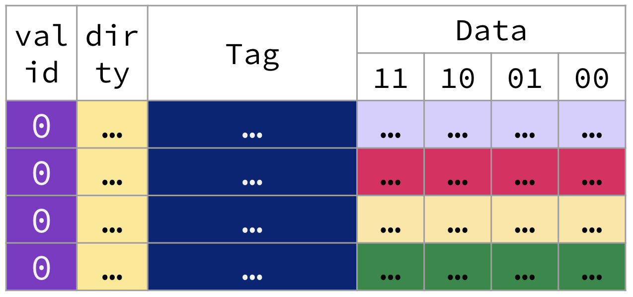
A cold snapshot of a 16B direct-mapped cache with 4B blocks and a dirty bit for write-back.
On the surface, the direct mapped cache looks very similar to that of our fully associative cache. We discuss how the direct mapped placement policy shortens the tag width and impacts the identification procedure to determine a cache hit.
Tag, Index, and Offset
The mapping of pretty much all direct-mapped caches is simple:
Like before direct-mapped caches copy in data from memory at the granularity of blocks. We can then translate from byte address to block addresses.
As an example, we can connect the direct-mapped cache in #fig-dm-valid to the 12-bit memory address in #fig-dm-address.
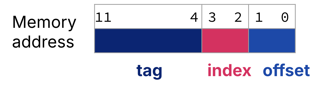
For a direct-mapped cache, the memory address is split into three fields: the tag, the index, and the offset. For the cache in #fig-dm-valid, a 12-bit memory address is split into an 8-bit tag, a 2-bit index, and a 2-bit offset.
- In a direct-mapped cache, the index is used to select the block.
- In direct-mapped caches, the tag is the upper bits of the address, excluding the bits for the index and the offset. The tag is used to check the cache block.
- As with all caches, the offset is the portion of the address needed to describe the byte offset within a block. These are always the lowest bits of the memory byte address.
- The block address is the tag concatenated with the index.
Solution
- 4 bytes.
- 16 bytes. Remember, data capacity.
- The offset is still with respect to the block size. = 2 bits.
- The index selects the entry of the cache. To index into each of the 4 entries of this cache, we need $\log_2{(\text{number of blocks})} = 2 bits.
- The tag, like before, is the upper bits of the address—but now, it is the upper bits that are not captured by the index and the offset. Because we use a 12-bit memory address in our toy example, for this direct-mapped cache our tags are (# address bits) - (# index bits) - (# offset bits) = 8 bits.
Replacement Policy
Show Answer
E. None of the above.
In direct mapped caches, there is only ever one block to replace—the existing block with matching index. LRU, most recently used, FIFO, and Random replacement would violate the placement policy of direct-mapped caches.
Write Policy
Show Answer
C. both A and B.
Direct-mapped placement policy does not impact our choice of when writes to memory happen. Both write-through and write-back policies are possible.
Walkthrough
The following animation traces through four memory accesses to a 12-bit address space on our 16B direct-mapped cache with 4B blocks. Assume a write-back policy. Assume the cache starts out cold, like in #fig-dm-valid.
Warming up a direct-mapped cache.
1. Load byte @ `0xFE2`. Cache miss.
Address 0xFE2 in binary: 0b1111 1110 0010
- Tag:
0b11111110, or0xFE - Index:
0b00, or0 - Offset:
0b10
- Cache Miss. The entry at index
0has an invalid tag. - Access lower level of memory hierarchy. Load into cache entry
0a block’s worth of data from memory starting @ address0xFE0(0b1111 1110 0000). Write the tag0xFE. Mark valid bit. Unset dirty bit. - Read. Read byte in cache block at offset
0b10and return to processor.
2. Store byte @ `0x61C`. Cache miss.
Address 0x61C in binary: 0b0110 0001 1100
- Tag:
0b01100001, or0x61 - Index:
0b11, or3 - Offset:
0b00
- Cache Miss. The entry at index
3has an invalid tag. - Access lower level of memory hierarchy. Load into cache entry
3a block’s worth of data from memory starting @ address0x61C(0b0110 0001 1100). Write the tag0x61. Mark valid bit. Unset dirty bit. - Write. Write byte in cache block at offset
0b00. Set dirty bit.
3. Load byte @ `0x61B`. Cache miss.
Address 0x61B in binary: 0b0110 0001 1011
- Tag:
0b01100001, or0x61 - Index:
0b10, or2 - Offset:
0b11
- Cache Miss. The entry at index
2has an invalid tag. - Access lower level of memory hierarchy. Load into cache entry
2a block’s worth of data from memory starting @ address0x618(0b0110 0001 1000). Write the tag0x61. Mark valid bit. Unset dirty bit. - Read. Read byte in cache block at offset
0b11and return to processor.
4. Load byte @ `0xCAD`. Cache miss.
Address 0xCAD in binary: 0b1100 1010 1101
- Tag:
0b11001010, or0xCA - Index:
0b11, or3 - Offset:
0b01
- Cache Miss. While the entry at index
3is valid, its tag0x61does not match the provided tag0xCA. - Access lower level of memory hierarchy. The existing valid block at cache entry
3must be replaced. Its dirty bit is set, so write this block to memory and replace it with a block’s worth of data from memory starting @ address0xCAC(0b01100 1010 1100). Write the tag0xCA. Mark valid bit. Unset dirty bit. - Read. Read byte in cache block at offset
0b01and return to processor.
Contrast this direct-mapped cache walkthrough with the one for fully associative caches:
- Identification of a cache hit occurs by checking exactly one tag: the tag at the indexed cache entry.
- Memory accesses 2 and 3 create cache entries in cache entries
3and2, respectively; these cache entries share the same tag. However, the blocks in these entries have different block addresses. - Memory access 4 still incurred a block replacement (and a cache write-back) even though the cache was not filled. The cache entry at index
3was occupied by a block with a different tag.
Direct Mapped: Hardware and Performance
Implementing a direct-mapped cache in hardware is much simpler than the fully associative cache.
- Because the block can only be in one location, on a cache hit we need just one comparator to check the tag in the target line (and one mux to get said tag). We no longer need one comparator per cache block/entry.
- Because the index is now used to select the location of the block in the cache, it is not encoded into the bits of the tag. This reduces the width of each tag, thereby reducing the overhead per cache entry.
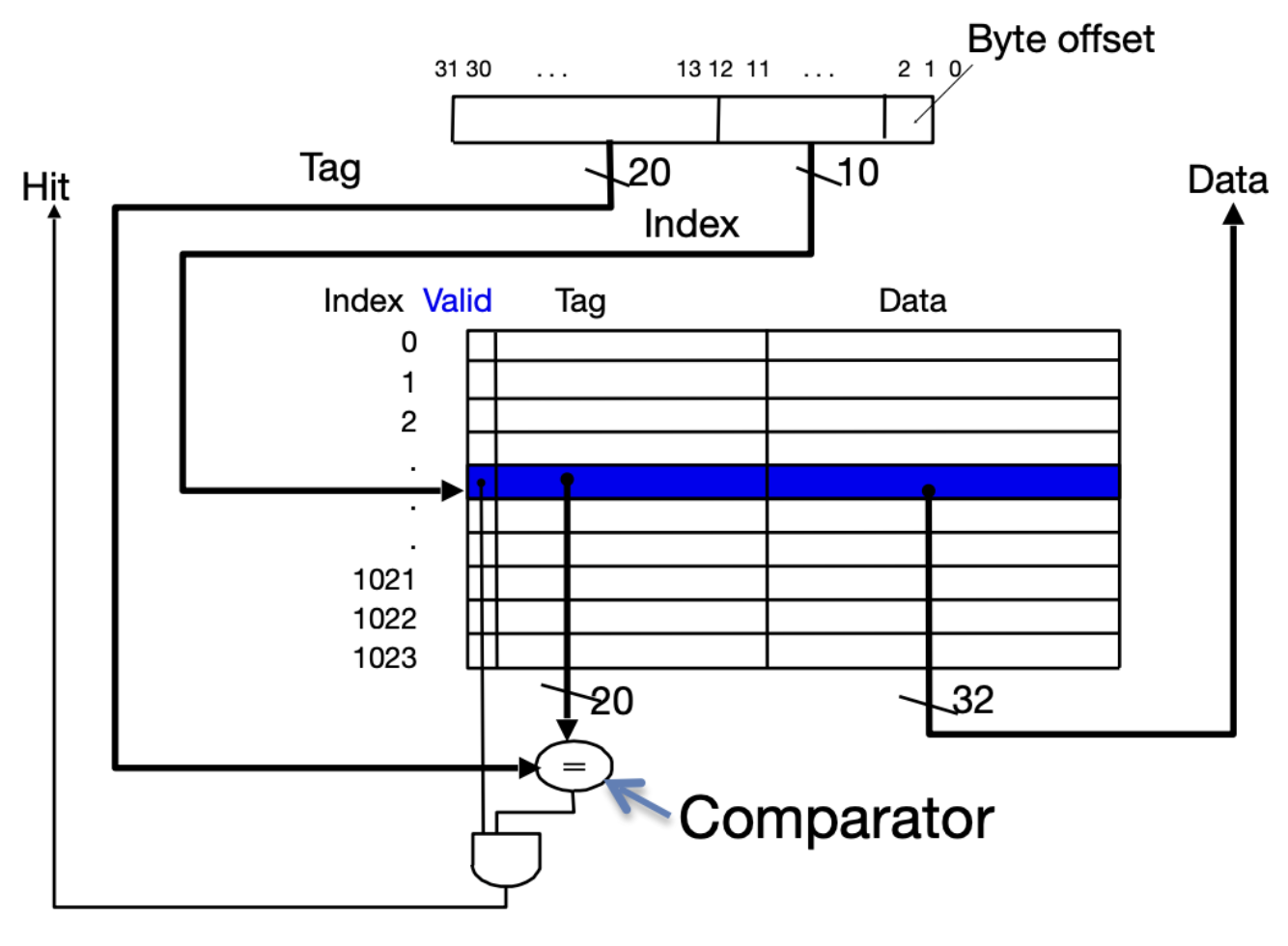
Hardware implementation of a direct-mapped cache.