Arithmetic Logic Unit
Learning Outcomes
- Design a basic Arithmetic Logic Unit (ALU).
- Use mux circuits in the ALU.
🎥 Lecture Video
🎥 Lecture Video
Most processor implementations include a special combinational logic block called an arithmetic logic unit (ALU). In RISC-V, the ALU is used to compute the result in the R-type instructions, such as, add, sub, and, or addi, ori, etc.
ALU Block
We are going to consider the design of a simpler version of the ALU than the one in our RISC-V processor. Ours will include only four basic functions:
- ADD
- SUB
- (bitwise) AND
- (bitwise) OR
This ALU is implemented as a combinational logic block in #fig-alu:
- two 32-bit wide data inputs,
AandB; - a 32-bit wide data output,
R; and - a 2-bit wide control input,
S
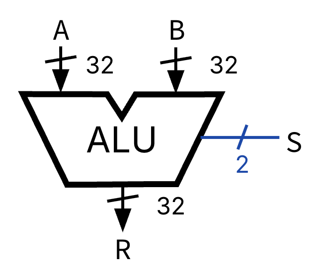
Basic ALU: ADD, SUB, AND, and OR
In our basic ALU, S is used to select R as one of the four operations:
ALU Circuit
The internal design of our simple ALU is shown in #fig-alu-circuit:
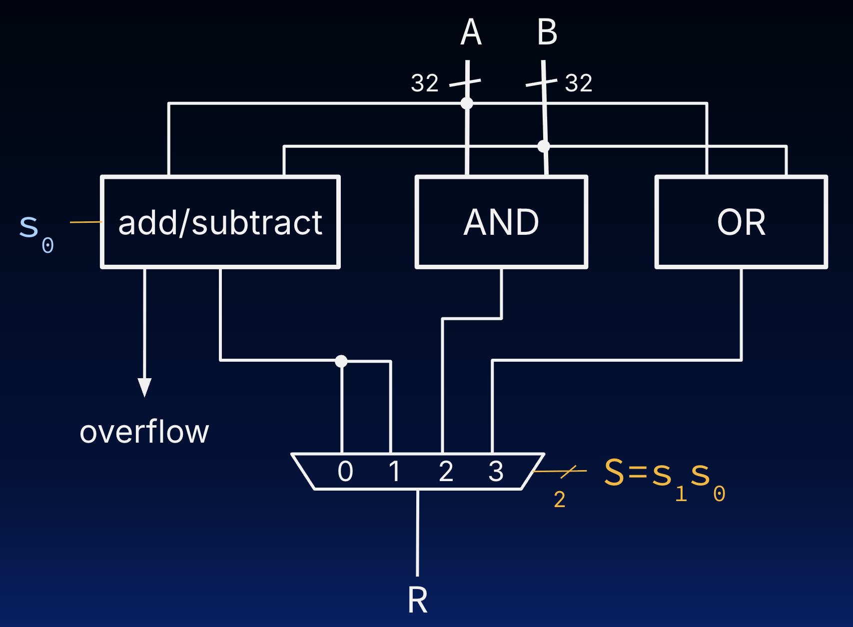
Basic ALU circuit with three blocks (AND, OR, add/subtract) and a 4-to-1 mux.
For our simple ALU we will need an add/subtract block, an AND block, and an OR block. Each of these blocks will take two 32-bit inputs and produce a 32-bit output. Read more about implementing these blocks below.
More Explanation
The high bit of S () and the low bit of S () are used to implement Equation #eq-alu:
- : The add/subtract block
- : Specify add; note that is therefore used for both the MUX and the add/subtract block.
- : Specify subtract
- : One of the AND or OR blocks
- : Specify AND
- : Specify OR
Implementing the Internal Blocks
The logical operations as defined by the RISC-V ISA are bitwise operations.
- AND: , is
&, for the -th bits of the outputR,A, andB, respectively. Perform this bitwise operation as a collection of 32 AND gates, where each AND gate is responsible for one of the 32 resultant bits. - OR: Similarly, the OR block is a collection of 32 OR gates.
- The add/subtract block is a significantly more complex block than the AND or OR blocks; its design is the subject of the next section. For now, we note that a subtractor circuit is very similar to an adder, hence why we provide a single circuit that is capable of either operation.
case of the AND, the resultant bit ri is generated as ai AND bi. The circuit to perform this operation is simply a collection of 32 AND gates. Each AND gate is responsible for one of the 32 resultant bits. Similarly, the OR block is a collection of 32 OR gates.