Logic Gates
Learning Outcomes
- Use truth tables to enumerate the input-output relationships of a basic logic gate and a combinational logic circuit.
- Describe the functionality of N-input logic gates (in particular, the 3-input XOR gate).
🎥 Lecture Video
🎥 Lecture Video
To design circuits that perform complex operations on binary signals, we must first define primitive operators called logic gates. Logic gates are simple circuits (each with only a handful of transistors) that can be wired together to implement any combinational logic function. In CS 61C we consider logic gates are primitive elements; they are the basic building blocks for our circuits.
The simplest logic gates are binary or unary operators that take as input one/two binary variables and output one binary value.
Common Logic Gates
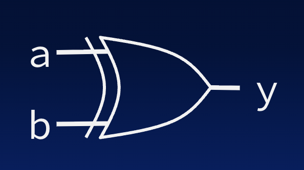
Here are some common logic gates, many of which you have already seen as C bitwise operations. For each we define its name, a graphical representation, and a truth table that defines its function.
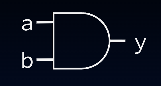
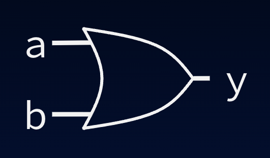

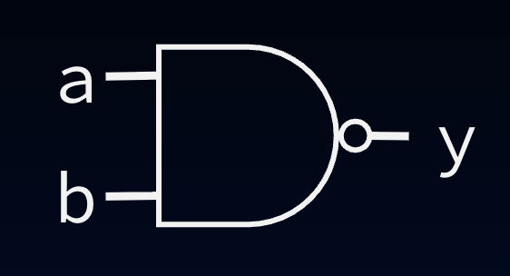
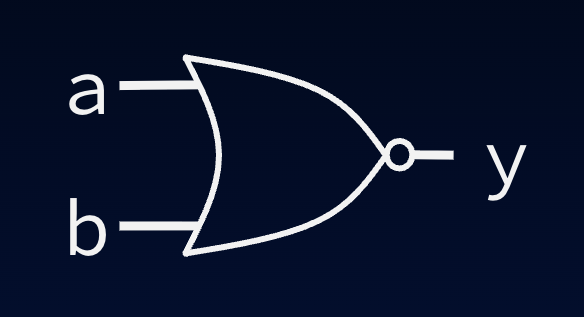
Notes:
- AND, OR, NOT and XOR follow from the C bitwise operations you learned eariler.
- The NOT gate is commonly called an inverter. Note the “bubble” (circle).
- NAND is “NOT” AND. Note the bubble on its output.
- NOR is “NOT” OR. Again, note the bubble.
N-Input Logic Gates
Except for NOT (which is a unary operator), we have shown 2-input versions of these common gates. Versions of these gates with more than two inputs also exist. For performance reasons, the number of inputs to logic gates is usually restricted to around a maximum of four.
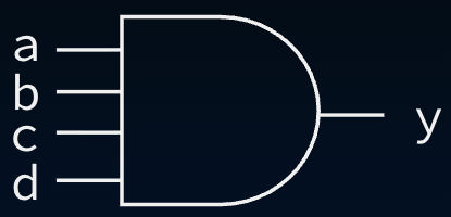
4-input AND gate. The output y is 1 if and only if a, b, and c are all 1.
The function of these gates with more than two inputs is obvious from the function of the two input version, except in the case of the the exclusive-or gate,
Except for NOT (which is unary), we have shown 2-input versions of these gates. Versions of these gates with more than two inputs also exist. However, for performance reasons, the number of inputs to logic gates is usually restricted to around a maximum of four.
The function of these gates is generally self-evident and can deterined by repeatedly composing the equivalent 2-input gate; for example, AND(a, b, c, d) = AND(AND(a, AND(b, AND(c, d)))) = AND(AND(a, b), AND(c, d)), etc. There are a few exceptions; let’s try your reasoning with some quick checks.
What is an N-input [NAND](#fig-nand-gate)?
An N-input NAND is NOT of an (N-input AND).
What is an N-input [NOR](#fig-nor-gate)?
An N-input NOR is NOT of an (N-input OR).
Designing Combinational Logic Circuits
Simple logic gates can be wired together to build useful circuits. In fact, any combinational logic block can be implemented with nothing but AND, OR, and NOT logic gates.
However, to understand what a circuit actually does, we need more than just its circuit diagram: we need a concise description of its operation.