Canonical Form, CL Design
Learning Outcomes
- Practice translating between the three representations for a combinational logic block: truth table, boolean expression, and gate diagram.
- Practice using laws of Boolean Algebra.
- Practice modular design: compose complex circuits using smaller circuits.
🎥 Lecture Video
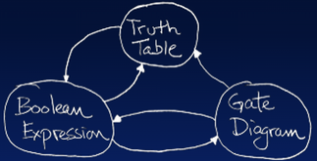
Our goal this lecture is to build combinational logic blocks. We can summarize this approach with the following diagram:
Second equivalent circuit: .
#fig-cl-block-representation shows the three possible representation for a combinational logic block.
- The truth table form is unique—for every combinational logic block, there is only one truth table. The uniqueness of the truth table makes it a useful way to clearly define the function of a combinational logic block.
- There are multiple Boolean expressions possible for any combinational logic block. Boolean expressions are useful for algebraic manipulation, particularly simplification.
- Multiple gate level representations for any combinational logic blocks. The gate diagram gives us a prescription for converting to an actual transistor circuit; each gate in the diagram can be replaced by a small transistor circuit that achieves is respective gate level function.
This section discusses how to translate between the diferent representations of a combinational logic block. This section ends with how to compose circuits from smaller blocks.
Example: Majority Circuit
Consider the below equation. This describes a three-input majority circuit because the output y takes on the value that matches the majority of the input values.
Equation #eq-majority-circuit has the corresponding truth table
and has the corresponding gate circuit
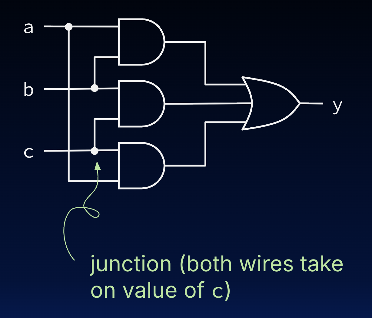
Circuit corresponding to .
The equation says that the output y is the OR () of three terms, where each term is the AND of two input variables ( or concatenation). The correspondence between #eq-majority-circuit and the circuit in #fig-majority-circuit should be clear. The three product terms are implemented using AND gates and the final sum by the three input OR gate.
Canonical Form
Let’s go back to the truth table as our definition of a desired function. Starting from a truth table, by inspection, it is possible to write a Boolean expression that matches its behavior. The type of Boolean expression that we will write is called the “sum-of-products” canonical form.
The canonical form gets its name from the fact that it is formed by taking the sum (OR) of a set of terms, each term being a product (AND) of input variables or their complements.
- Every place (row) where a 1 appears in the output, we will use a product (AND) term in the Boolean expression.
- Each AND term includes all the input variables in either complemented or uncomplemented form.
- A variable appears in complemented form if it is a 0 in the row of the truth table, and as a 1 if it appears as a 1 in the row.
Example: Truth Table Boolean Expression Gate Diagram
Any CL circuit that can be practically specified as a truth table can be represented with a Boolean expression by writing its canonical form. Following that, through algebraic manipulation, it can be simplified, then translated to a circuit of logic gates.
1. Use the truth table to build the canonical form. The canonical form equation has four product terms, one for each of the 1’s in the output .
Click to show annotated truth table
| PRoduct | ||||
|---|---|---|---|---|
| 0 | 0 | 0 | 1 | |
| 0 | 0 | 1 | 1 | |
| 0 | 1 | 0 | 0 | |
| 0 | 1 | 1 | 0 | |
| 1 | 0 | 0 | 1 | |
| 1 | 0 | 1 | 0 | |
| 1 | 1 | 0 | 1 | |
| 1 | 1 | 1 | 0 |
2. Simplify using Boolean Algebra laws, if needed.
3. Draw the gate diagram. The circuit specified by the canonical form is one of many circuits that implement the original 3-input function.
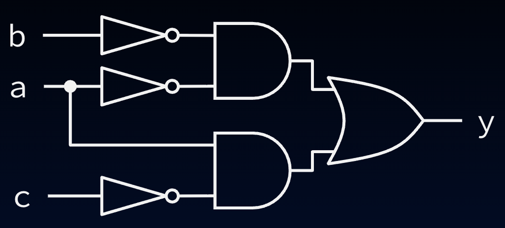
Circuit specified by canonical form in example.
Example: Simplify Circuits
Simplifying circuits involves taking a gate diagram and writing its Boolean expression, simplifying it, then translating back to a gate diagram.
Example: Verify Circuit (Majority Circuit, Revisited)
In our three-input majority circuit, we can use the truth table to build the canonical form:
Click to show annotated truth table
We can then use Boolean algebra to verify that the canonical form is equivalent to the intuitive majority circuit equation:
Example: Gate Diagram Truth Table
To generate a truth table from a given circuit, we just need to evaluate the output for all possible input combinations.
Truth Table:
| a | b | y |
|---|---|---|
| 0 | 0 | 1 |
| 0 | 1 | 0 |
| 1 | 0 | 0 |
| 1 | 1 | 1 |
Show Explanation
- Top AND gate: This gate output is
1only ifaandbare both1. - Bottom AND gate. Because of the two NOT gates right before input, this gate output is
1only if NOTaand NOTbare both1, i.e.,aandbare both0.2 - OR gate. The output
yis1if at least one of the AND gates is1.
2-Bit Compare
After some thought, you may have realized that this combinational logic circuit can be described as a compare: Take two inputs and returns 1 if the two inputs are equal and 0 otherwise. We use this functionality in a later example.3
Composing Circuits: 32-Bit Comparator
We would like to a circuit that compares two 32-bit values; this 32-bit compare circuit can be used in our processor to implement the equality comparison for the RV32I instruction beq rs1 rs2 Label.
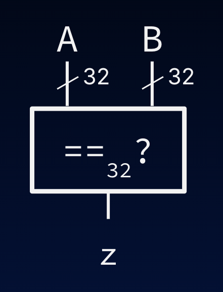
32-bit compare circuit.
We’d therefore like to use the 2-bit compare circuit we built in a previous example. We represent the circuit as a combinational logic block, as below. This block helps abstraction; any time you see the block in #fig-compare-2-block, know it is implemented as the circuit in #fig-compare-2-circuit.
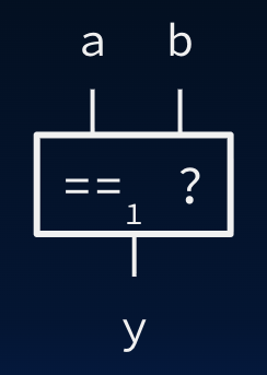
Bitwise compare circuit; a block representation of the mystery circuit in #fig-compare-2-circuit.
By way of comparison, for the 32-bit compare circuit(@fig-compare-32-block):
- The value
Ais a 32-bit value, because of the wire bundle (the wire is marked with a notch). Similarly, valueBis 32-bits. - The value
zis a 1-bit value.
Functionally, z is 1 only if all of A’s bits are equal to all of B’s bits. In other words, we can perform 32 bitwise comparisons, then AND them together. The underlying circuit for our compare block is therefore as follows:
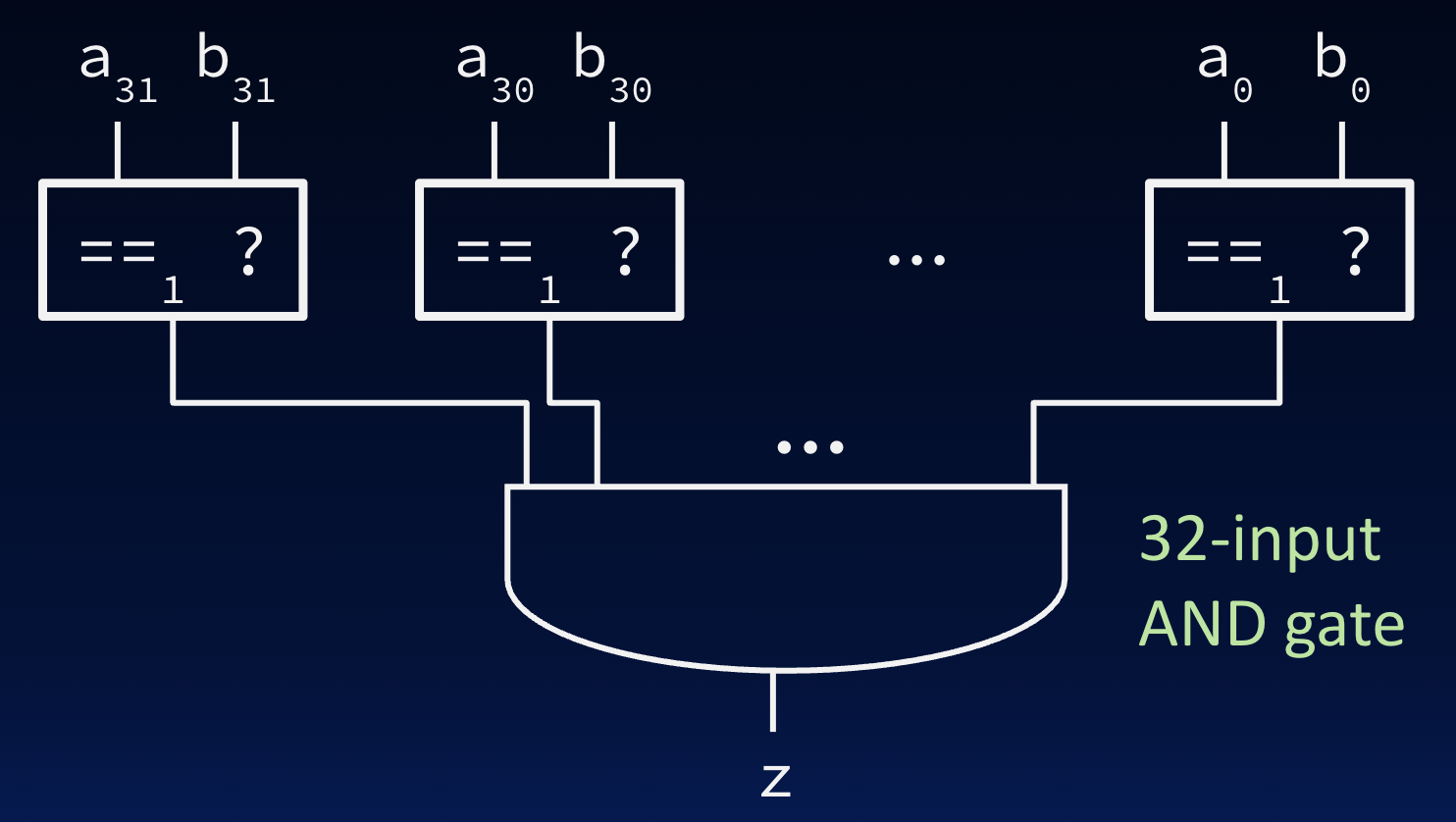
32-bit compare circuit diagram, assuming we have implemented the bitwise compare circuit. The 32-input AND gate can be implemented recursively with 2- or 4-input AND gates.
Footnotes
-
In fact, “exactly” one, because input combinations are unique. In Sum-of-Products we opt for OR (instead of “XOR”) in order to simplify expressions with laws of Boolean Algebra. ↩
-
Notably, this circuit is not a NAND gate; we leave the proof to you. We suggest writing things out with truth tables. ↩
-
We note that the outputs of the two AND gates will never both be
1, so we could have replaced the OR gate with an XOR gate. ↩