Data Multiplexors
Learning Outcomes
- Draw an n-bit wide, k-to-1 mux circuit.
- Explain how the mux uses its control signal to select its output from a set of data inputs.
🎥 Lecture Video
Last time we saw how to represent and design combinational logic blocks. In this section we will study a few special logic blocks; data multiplexors, a adder/subtractor circuit, and an arithmetic/logic unit.
The Mux
A data multiplexor, commonly called a mux or a selector, is a circuit that selects its output value from a set of input values. Below are two mux circuits.
:::::{grid} 2
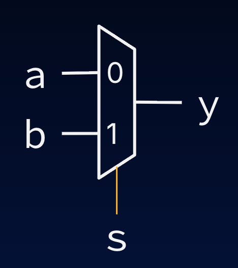
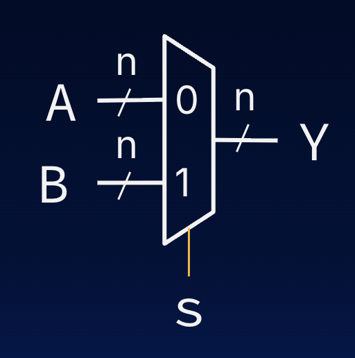
Both of these muxes have two data inputs and one output. Additionally, each mux has a special control signal labeled s, for select. The s signal is also input, but it is used to control which of the two input values is directed to the output.
#fig-mux-2 shows a 1-bit wide, 2-to-1 mux circuit:
- 2-to-1 because it takes two data inputs
aandband outputs one of them. - It is 1-bit wide because all data signals (
aandb) are 1-bit in width. - Notice, however, that the
ssignal is a single bit wide. This is because it must choose between the 2 inputs.
#fig-mux-n shows an n-bit wide, 2-to-1 mux circuit:
- 2-to-1 because it takes two data inputs
AandBand outputs one of them. - It is 1-bit wide because all data signals (
AandB) are 1-bit in width. - The
ssignal is still a single bit wide because it must choose between the 2 inputs.
The function of, say, the 1-bit wide 2-to-1 mux can be described with two rules:
To remind us of which value of s corresponds to which input, within the mux symbol we commonly label each input with its corresponding s value.
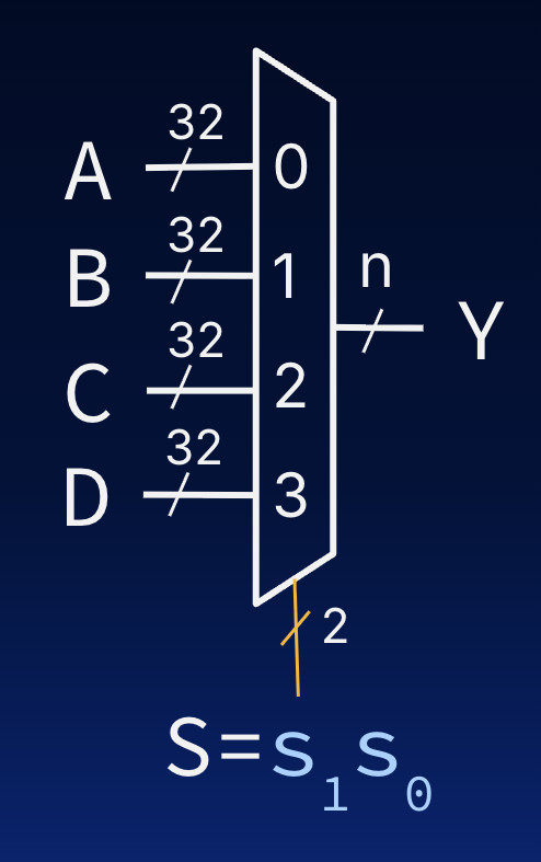
Muxes find common use within the design of microprocessors, e.g., those that implement RISC-V.
MUX: Implementation
In most applications, you will have access to a mux; you will not need to build your own from scratch. Nevertheless, it is good to remember that like all combinational logic blocks, the function of muxes can be described using a truth table and thereby implemented as a logic gate circuit.
1-bit wide, 2-to-1 MUX
How do we implement the mux in #fig-mux-2, discussed above?
This circuit can be expressed in Boolean algebra:
Expand the dropdown items below to show the gate circuit and derive the above expression.
Show Gate Diagram
#fig-mux-2-circuit shows the gate diagram for a 1-bit wide, 2-to-1 mux with inputs a and b and output c. Below, .
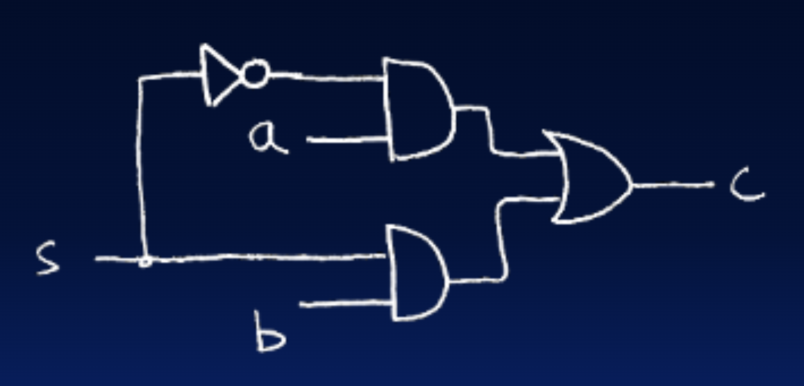
Gate diagram for a 1-bit wide, 2-to-1 mux.
Show Boolean Algebra Explanation
To come up with the logic equation and the associated gate-level circuit diagram we can apply the technique that we studied last chapter. We write the sum-of-products canonical form and simplify through algebraic manipulation:
Intuitively this result makes sense; When the control input, s, is a 0, the expression on the right-hand side of the expression reduces to a, and when it is a 1, the expression reduces to b.
1-bit wide 4-to-1 mux
Often times we find the need to extend the number of data inputs of a multiplexor. For instance consider a 4-to-1 multiplexor in #fig-mux-4-bits:
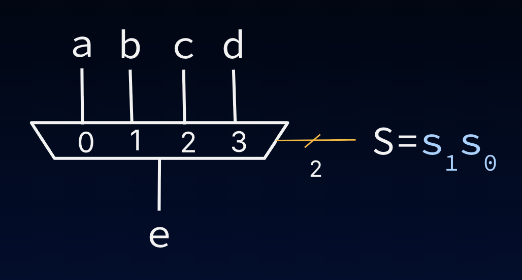
A 1-bit wide 4-to-1 MUX.
#fig-mux-4-block shows how this larger mux can be formed by wiring together smaller MUXes.
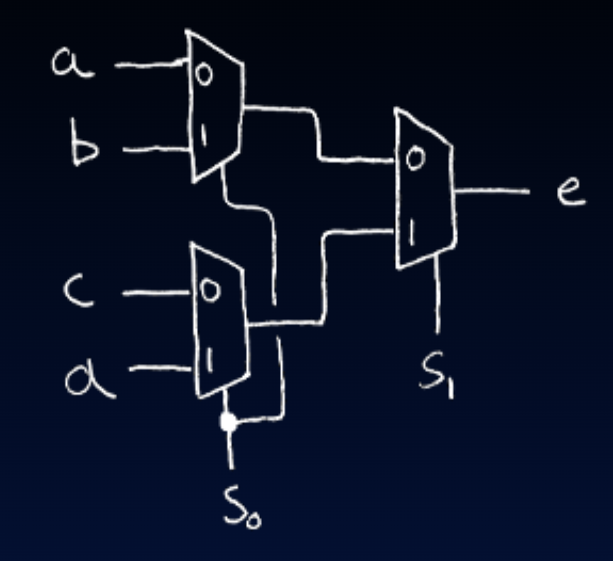
4-to-1 multiplexor (MUX) circuit diagram.
This circuit design leverages the hierarchical nature of multiplexing. The first layer of muxes uses the input to narrow the four inputs down to two, then the second layer uses to choose the final output.
Show Boolean Algebra Approach
An alternate approach could start by enumerating the truth- table—in this case the function has 4 single bit data inputs and one 2-bit wide control input, for a total of 6 single bit inputs. The truth table would have 26, or 64 rows. Certainly, a feasible approach. If we were to do this, we would end up with the following logic equation:
+ \overline{s_1} s_0 b + s_1 \overline{s_0} c + s_1 s_0 d$$ </details>