Synchronous Digital Systems
Learning Outcomes
- Define a synchronous digital system.
- Identify that transistors and wires are key to digital circuits.
- Identify two types of digital circuits: combinational logic circuits and memory circuits.
🎥 Lecture Video: Introduction
until 5:35
Now, we move below the orange line of our Great Idea #1. How do we design the hardware needed to execute machine code? In the next part of this course, we will implement a RISC-V processor as a synchronous digital system, which should have the capabilities to execute RISC-V instructions.
Great Idea #1: Abstraction.
Core (heh) to the modern computer are many types of integrated circuits, which themselves are composed of many interconnected synchronous digital systems (among other things). For example, the Apple A14 Bionic chip is used in many of Apple’s iPad and iPhone devices in the early 2020s.
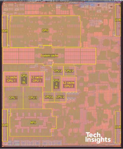
Apple A14 Bionic Chip (sources: Wikipedia, TechInsights)
Notice the various blocks labeled on the photograph. We will be discussing these later this semester. Here are the specifications for this particular processor:
- 11.8 billion transistors
- 5W power consumption
- Six cores (ARM v8.5a) up to 3.0 GHz:
- Two high-performance, Four energy-efficient
- CPU supports 64-bit data
- GPU for working with graphical data
- NPU “Neural Engine” dedicated neural net HW
- AMX matrix scalar multiplication accelerators
- L2 cache: 4-8MB
In this class, we focus on the central processing unit (CPU), or processor (the left side of our computer layout figure). To understand how a modern processor is built, we start with definitions of the basic building blocks.
Wires and Transistors
All circuits are made from wires and transistors.1
- Wires (i.e., electrical nodes) provide electrical signals and are used to represent variables.
- Transistors are semiconductor devices to amplify or switch signals.
Wires
In digital circuits, each wire can take on one of two values via a binary representation of voltage levels to signal 0 or 1. At a high-level, wires that have ample current running through them will be pulled to a “high” voltage and represent 1; wires pulled to “low” voltage represent 0.
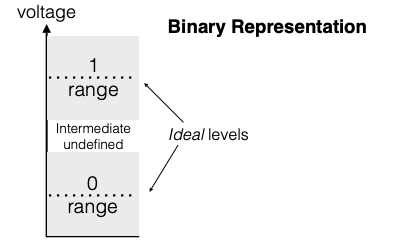
Low voltage is 0; high voltage is 1.
For digital circuits, we keep signals simple (i.e., binary values only) and push complexity later into how we combine signals. Bundles of wires represent multi-bit variables (@fig-bin-rep-signals).
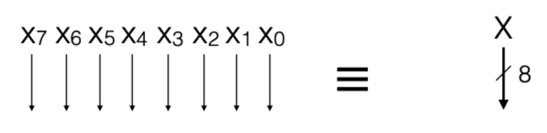
(left) eight wires, each representing binary variables to ; (right) one bundle of wires representing an 8-bit variable .
Why not go beyond a binary signal representation?
Early computers represented signals as decimals–not binary. However, all wires subject to interference/non-idealities, which grows worse at smaller sizes.
As chips get more complex, wires get smaller. Circuits to discriminate between two possible inputs are simple to implement and have scaled well with Moore’s Law. Binary representations for signals therefore produce reliability via good noise immunity.
A wire can take different (binary) values at different points in time. Wires are pulled to low and high voltages by transistors.
Transistors, briefly
Transistors are in all modern electronics: integrated circuits and microprocessors. The evolution and design of the transistor is discussed in Great Idea #2: Moore’s Law, which shows the growth over time of (micro)processor transistor density.
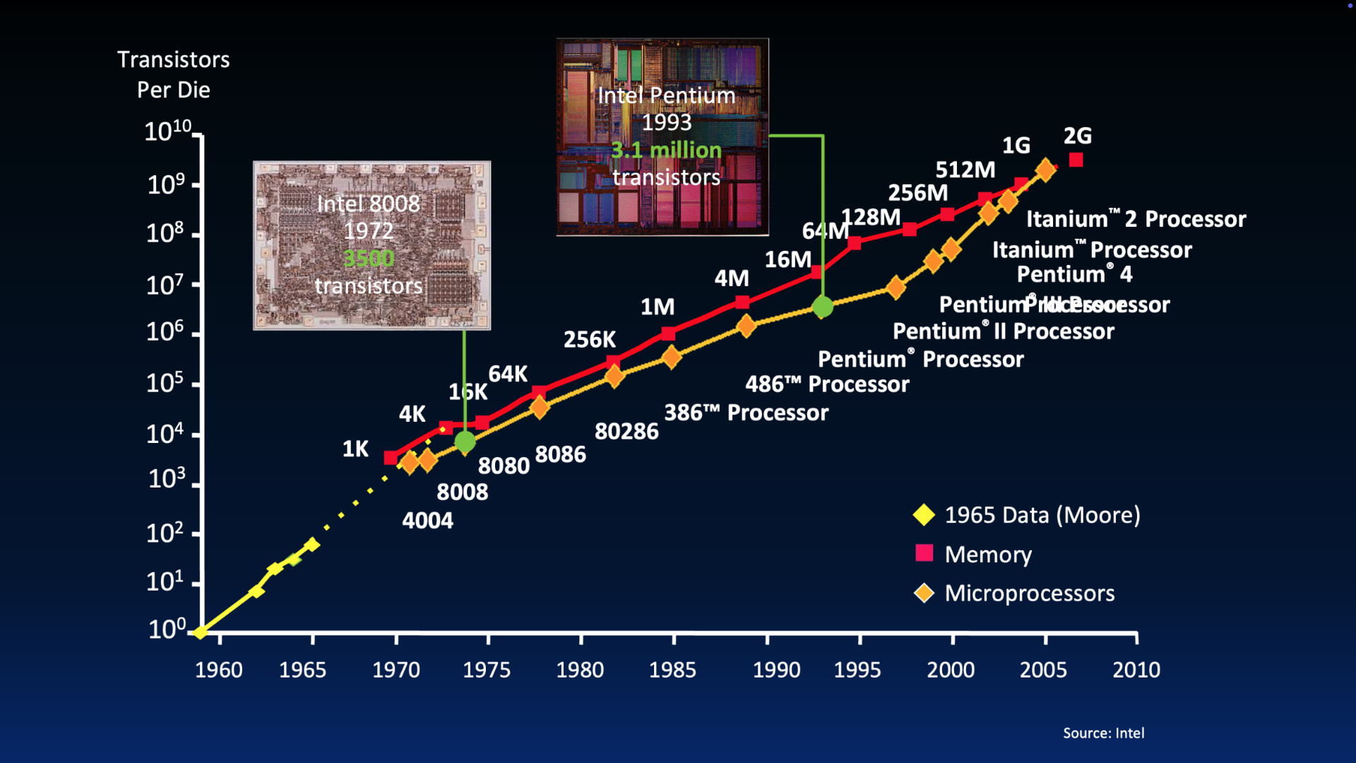
Visual of Moore’s Law over time.
Intel Cofounder Gordon Moore2:
“Reduced cost is one of the big attractions of integrated electronics, and the cost advantage continues to increase as the technology evolves toward the production of larger and larger circuit functions on a single semiconductor substrate.”
— Electronics, Volume 38, Number 8, April 19, 1965
Understanding the transistor is beyond the scope of our course. For those curious, we have included a bonus section on transistors and switches, though we recommend you take advanced coursework like EE 105: Microelectronic Devices and Circuits.
We will focus on remembering that transistors are critical to composing building blocks used for designing processor logic. Because of their switching and amplifying behavior, they can be composed together to design circuits that perform logic on binary variables (again, wires) and store state of specific binary values.
Example digital circuit: NAND
Consider NAND, which takes two binary inputs and produces a binary output that is 0 (low) only if both the two inputs are high (1).
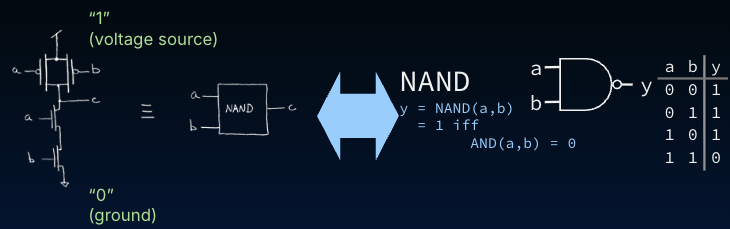
NAND gate. We will mostly use the representations on the right-hand-side.
There are five NAND representations shown in #fig-equivalence-nand. In this course, we focus on the four rightmost representations.
- (leftmost): Transistor circuit diagram of a NAND gate with inputs
aandband outputc - (immediately left of arrow): Block diagram of NAND, again with inputs
aandband outputc - (immediately right of arrow) Functional description of NAND, where
y = NAND(a, b) - (second from the right) NAND logic gate, with inputs
aandband outputy - (rightmost): Truth table for NAND, with inputs
aandband outputy
Synchronous Digital Systems
The hardware underlying almost every processor is a Synchronous Digital System.
We discuss the clock later. For now, know that a clock can also be represented via a digital “square wave” signal, oscillating between 1 and 0 periodically. Nowadays, clocks operate in the 3-4GHz range, meaning there are four billion periods of this square wave per second. We will see later how a clock supports state.
Click to show alternatives to SDS
- Asynchronous systems must locally coordinate actions and communications b/t components; much harder to design/debug.
- Analog circuits use voltage/current to represent continuous ranges of values. These days, even a lot of analog circuitry uses synchronous digital design by using analog-to-digital converters, and vice versa. Take EE 105 for more information!
Types of Digital Circuits
Synchronous Digital Systems consist of two basic types of circuits: combinational logic circuits and stateful circuits.
Combinational logic circuits take their inputs and combine them to produce a new output after some small delay. The core components of combinational logic circuits are logic gates.
Combinational logic circuits have no memory of their previous inputs or outputs. The output is a function of nothing other than the inputs—like a mathematical function, e.g., . Combinational logic circuits have no way to store information from one invocation to the next and do not generate any side effects.
Combinational logic circuits are used throughout processor implementations. They provide all the necessary functions needed to execute instructions, including all the arithmetic and logic operations, incrementing the program counter value, determining when to branch, calculation of new PC target values, etc. Not counting the area consumed by caches, _most of the area on microprocessor chip_s is used for combinational logic blocks.
State elements, or memory circuits, are circuits that store information. Unlike combinational logic circuits, these circuits remember their inputs (in CL, inputs are only used to generate outputs, but never remembered). The core component of stateful circuits are state elements. We discuss one such state element, the register, in detail in a later section.