The RISC-V 5-Stage Pipeline
Learning Outcomes
- Explain how pipeline registers pass data in-between stages of the 5-stage pipeline.
- Contrast the ways that the five-steps of a RISC-V instruction are implemented in a 5-stage pipelined processor and a single-cycle processor.
- Discuss approaches to pipelining control.
🎥 Lecture Video
In this section, we transform the single-cycle processor into our RISC-V five-stage pipelined processor. A pipelined processor “separates” the five steps to a RISC-V instruction into stages, where instructions execute in stages, and stages of different instructions execute in parallel during the same clock cycle.
Pipelined Datapath
Toggle between the visualizations below to visualize the five-stage pipelined datapath. At each rising clock edge, pipeline registers carry data and control signals to the next stage. We discuss control below.
5-Stage Pipelined Datapath
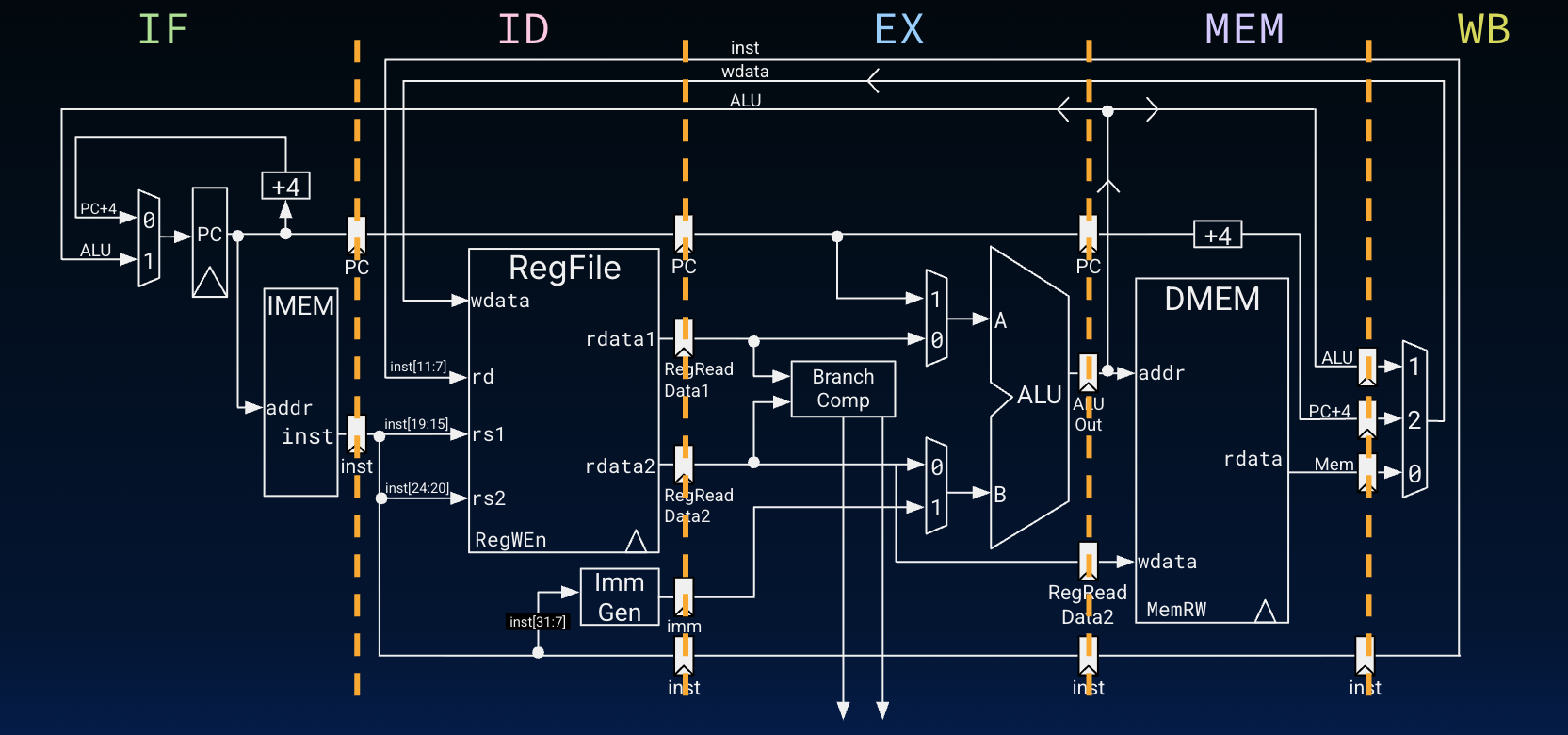
Five-stage RISC-V datapath diagram. Pipeline registers are inserted between stages to hold signals until the next clock cycle.
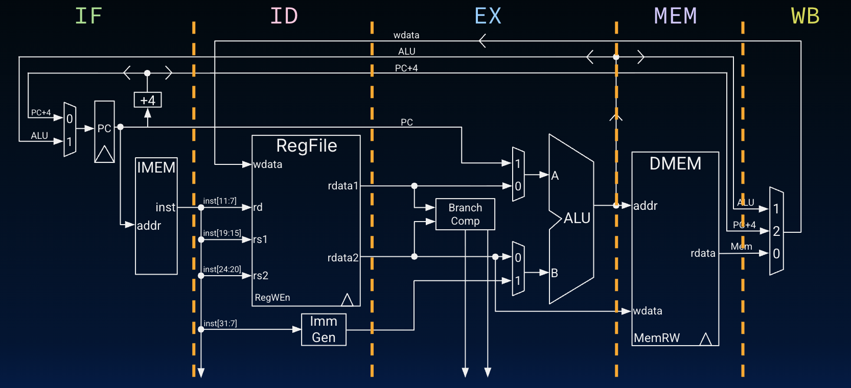
Just like the single-cycle datapath, in the five-stage pipeline, data and control signals still generally move left to right. There are also still two loops. We extend our original quote from P&H 4.7:
Instructions and data move generally from left to right through the five stages as they complete execution. Returning to our laundry analogy, clothes get cleaner, drier, and more organized as they move through the line, and they never move backward.
There are, however, two exceptions to this left-to-right flow of instructions:
- The write-back stage, which places the results back into the register file in the middle of the datapath
- The selection of the next value of the PC, choosing between the incremental PC and the branch address from the MEM stage
Data flowing from right to left do not affect the current instruction; these reverse data movements influence only later instructions in the pipeline. Note that the first right-to-left flow of data can lead to data hazards and the second leads to control hazards.1
We define pipeline registers by the two stages they are inserted between, e.g., IF/ID pipeline registers refer to the registers between the IF and ID stages. From P&H 4.7:
Returning to our laundry analogy, we might have a basket between each pair of stages to hold the clothes for the next step.
Five Stages of the RISC-V Pipelined Processor
We now revisit the five steps to a RISC-V instruction in the context of our new five-stage pipelined datapath in #fig-five-stage-pipeline. Here are the five steps.
And here are the stages of the five-stage RISC-V pipelined processor, one step per stage.
Pipeline Registers in the 5-Stage Datapath
Below, we explain #fig-five-stage-pipeline-registers from the perspective of what is fed into each set of pipeline registers. For example, when discussing IF/ID registers, we describe the instruction currently executing in the IF stage.
`IF/ID`: Show Explanation
An instruction that is currently in the IF stage passes the following into IF/ID pipeline registers:
PC: The PC (i.e., address of this instruction) is saved in case it is needed in a later clock cycle, e.g., in theEXstage, where conditional branch/unconditional jump instructions use the ALU to compute PC-relative addresses.inst: The instruction data, which is read from IMEM during this stage, is saved for immediate use in the instruction’s next stage,ID, e.g., to determine source registers. Recall that in theIFstage, the computer cannot know which type of instruction is potentially being fetched, so it must prepare for any instruction, passing potentially needed information down the pipeline (P&H 4.7).
`ID/EX`: Show Explanation
An instruction that is currently in the ID stage passes the following into ID/EX pipeline registers:
PC: Unchanged but may still be needed by this instruction in a later stage (seeIF/IDdiscussion). We pass this data directly between theIF/IDandID/EXpipeline registers.RegReadData1: Therdata1output signal from RegFile read during this instruction’sIDstage.RegReadData2: Therdata2output signal from RegFile, read during this instruction’sIDstage.imm: The output of the immediate generator, produced in this instruction’sIDstage.inst: Again, we pass the instruction along with its data onto the instruction’s next stage,EX.
`EX/MEM`: Show Explanation
An instruction that is currently in the EX stage passes the following into EX/MEM pipeline registers:
PC: Unchanged as part of this instruction’sEXstage but may be needed in later cycles of this instruction, e.g., withauipc.ALUOut: The ALU result, computed during this stage.RegRead2: The data in registerrs2; if this instruction is a store (S-Type), it will need this data in itsMEMstage.inst: Again, we pass the instruction along with its data onto the instruction’s next stage,MEM.
`MEM/WB`: Show Explanation
An instruction that is currently in the MEM stage passes the following into MEM/WB registers.
ALU: Unchanged in this instruction’sMEMstage, but needed as one of the options to write back to the RegFile in this instruction’s next stage,WB.PC+4: To avoid sending bothPCandPC + 4down the pipeline, we add an additional subcircuit to recalculatePC + 4as one of the write-back options in this instruction’s next stage,WB.Mem: The result of reading DMEM, read in this stage.inst: We are repeating ourselves here. :-)
Pipelined Control
Since pipelining the datapath leaves the meaning of the control lines unchanged, we can use the same control values but now group together the control signals by pipeline stage, as in #tab-controller-signals-pipeline and #fig-five-stage-control.
We note there is nothing special to control in the IF stage, because the control signals to read instruction memory and to write the PC are always implicitly asserted.
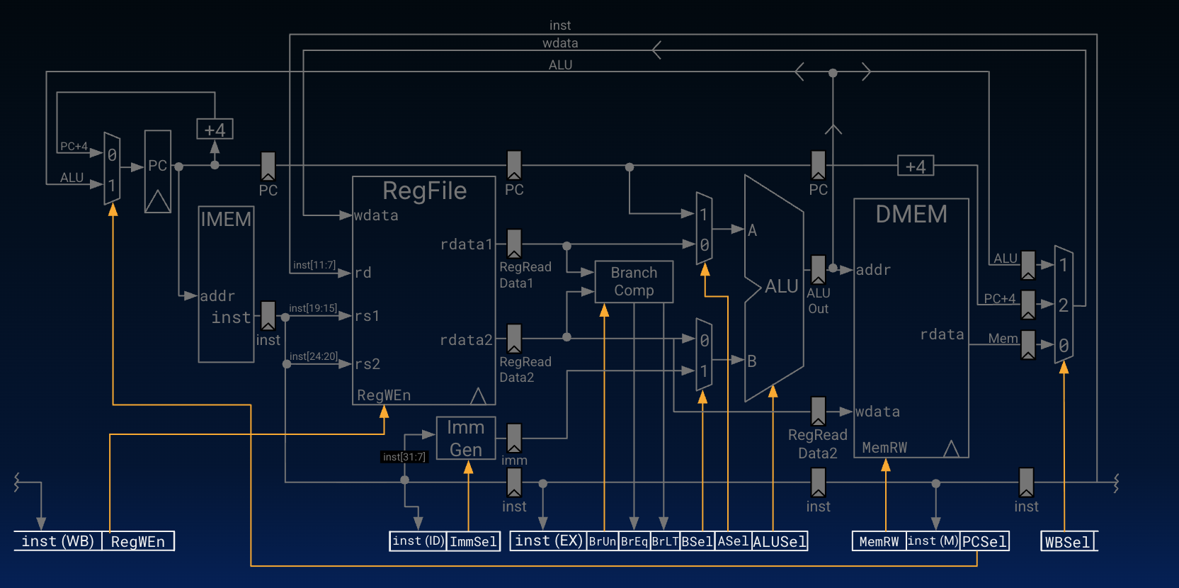
Five-stage RISC-V processor diagram with control.
Implementing Pipelined Control
Implementing control means setting these control lines to the correct values in each stage for each instruction.
#fig-five-stage-control above shows a one approach. Each stage now has a separate control unit that determines the control signals based on the instruction currently executing in that stage. This is illustrated by the inputs to the different control signal groups: inst (ID), inst (EX), inst (M), and inst (WB).
Click to show a second approach.
Another approach computes as many control signals as possible during instruction decode (ID) because all control signals but PCSel can be derived from the instruction. As shown in #fig-pipelined-control, this extends the pipeline registers to include control information to pipeline control “words” between stages. This approach reuses much of the control circuitry from our single-cycle processor, but it breaks from the grouping in #tab-controller-signals-pipeline.
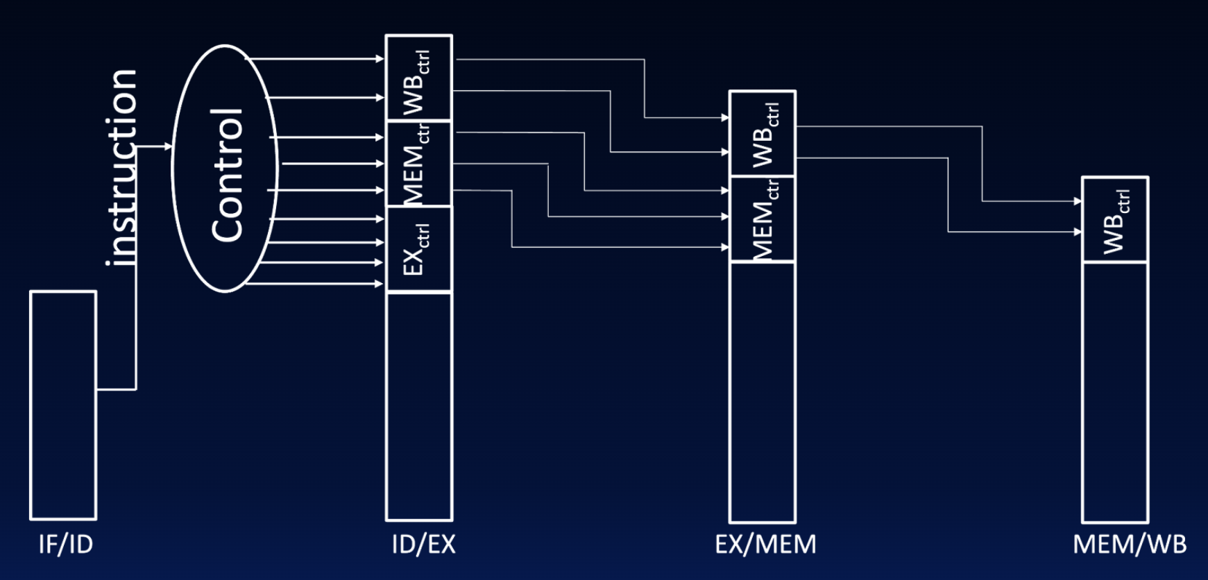
Diagram of additional pipelined register for control.
Summary
The full five-stage pipeline processor is shown in #fig-five-stage-summary; this is also on the course reference card.
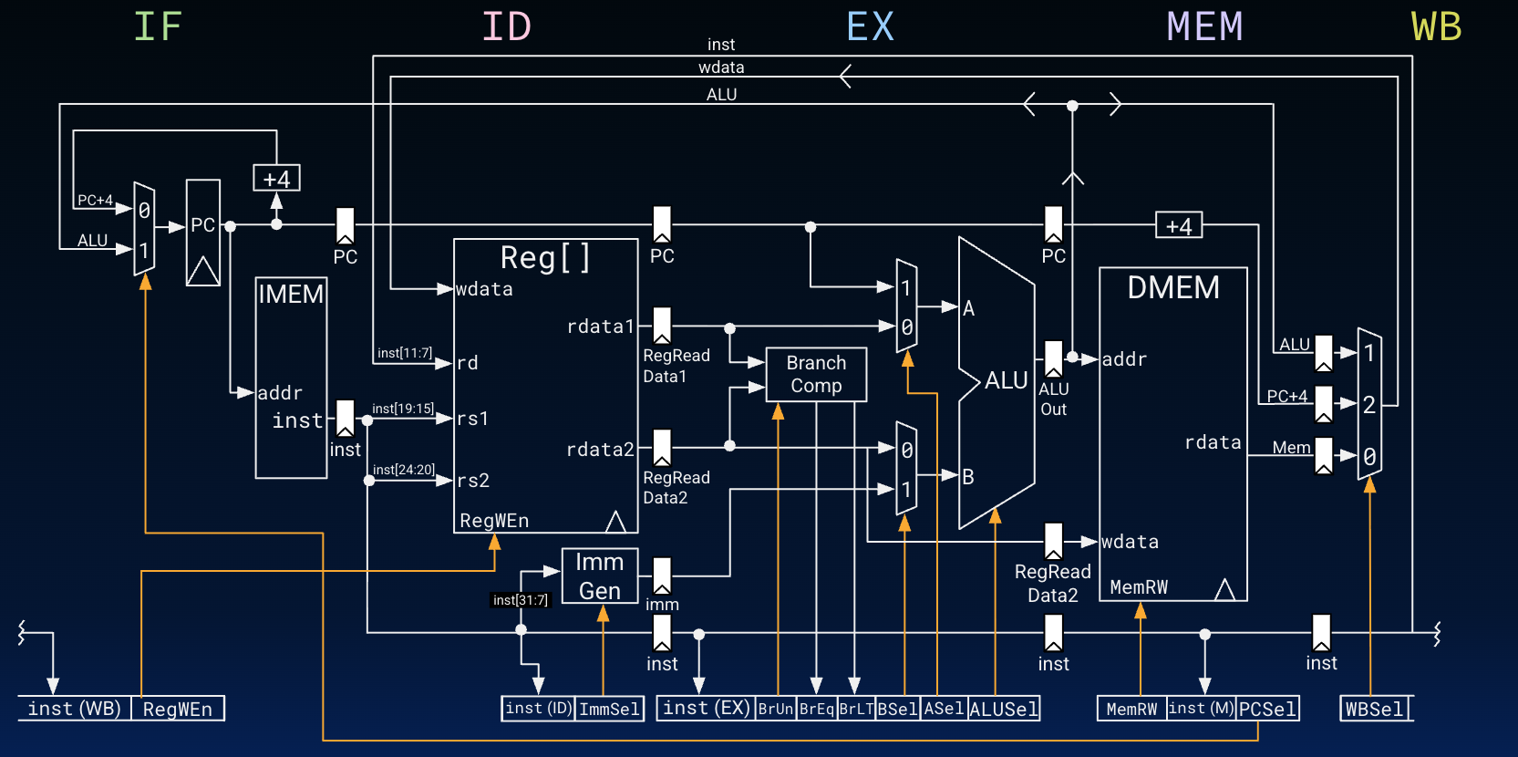
Five-stage RISC-V processor diagram: datapath and control.
The 5-stage pipeline we have studied is commonplace in many devices: cars, appliances, etc.