Supporting Jumps
Learning Outcomes
- Implement a datapath that supports unconditional jumps (
jalandjalr). - Compare the control signals set for
jalandjalr. - Explain why unconditional jumps do not use the branch comparator.
🎥 Lecture Video
🎥 Lecture Video
Datapath updates for jal
To support jal:
- RegFile: We read no registers but write one register
rd. The value to write ispc + 4, i.e., the “link” to the next instruction. - PC: We read from and write to PC. The value to write is
pc + imm.
We can reuse many components of our R-, I-, S-, and B-Type datapath. We will need to update two blocks, shown in #fig-jal-new-blocks.
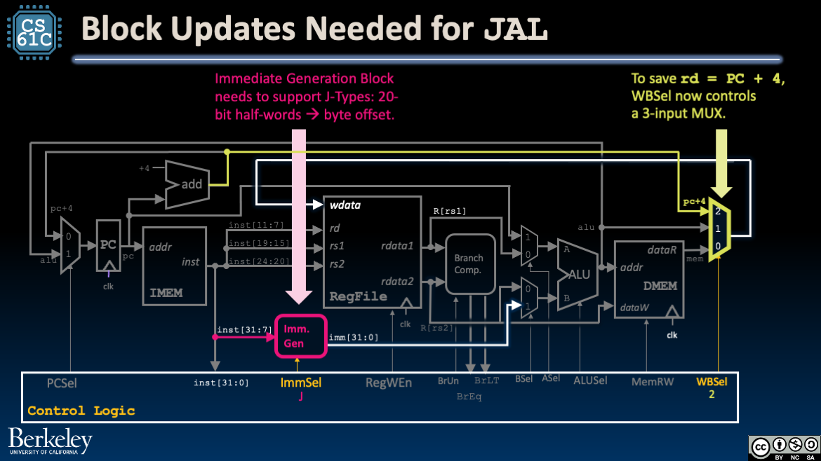
Update the Immediate Generator block and the WBSel mux.
Immediate Generator: Upgrade the Immediate Generator to support immediates in J-Type instructions.
Mux: The WBSel mux must now select between three values for wdata (the data to write to R[rd]):
- Arithmetic and Logical R-Type or I-Type instructions: The output of the ALU (
alu), which is now wired both intoaddrand into the new mux. - Load instructions: The output of DMEM (
mem). - Jump instructions:
pc + 4.
Tracing the jal Datapath
-
Instruction Fetch: At the beginning of the clock cycle, read PC and fetch the current instruction from IMEM. Feed
pcandpc + 4to blocks.Before the next rising clock edge, set the output of the ALU to the input of PC.
-
Instruction Decode: Build the immediate
immfor J-Type instructions. Also configure control logic (see below). -
Execute: Compute
pc + immusing the ALU. Because control signals areASel=1andBSel=1, the two muxes before the ALU will selectpcandimm, respectively. BecauseALUSel=Add, these two values will be added together using the ALU to producepc + imm. -
Memory: (We don’t access DMEM, so skip this.)
-
Write Back: Write
pc + 4output to the destination register by connecting the output of theWBSelmux to RegFile’swdatainput.Around the next rising clock edge,
wdata,RegWEn, andrdshould be held stable through setup and hold time of RegFile.
Datapath updates for jalr
To support jalr:
- RegFile: We read one register
rs1and write one registerrd. The value to write ispc + 4, i.e., the “link” to the next instruction. - PC: We read from and write to
PC. The value to write isR[rs1] + imm.
We do not need any updates to our datapath to support jalr! Because jalr is I-Type, the immediate generator block already supports it. Instead, for jalr, we need to set our control signals accordingly.
Tracing the jalr Datapath
-
Instruction Fetch: At the beginning of the clock cycle, read PC and fetch the current instruction from
IMEM. Feedpc + 4to blocks.Before the next rising clock edge, set the output of the ALU to the input of PC.
-
Instruction Decode: Fetch
R[rs1]from RegFile and build the immediateimmfor I-Type instructions. Also configure control logic (see below). -
Execute: Compute
R[rs1] + immusing the ALU. Because control signals areASel=0andBSel=1, the two muxes before the ALU will selectR[rs1]andimm, respectively. BecauseALUSel=Add, the ALU will add these two values together. -
Memory: (We don’t access DMEM, so skip this.)
-
Write Back: Write
pc + 4output to the destination register and connect the output of theWBSelmux to RegFile’swdatainput.Around the next rising clock edge,
wdata,RegWEn, andrdshould be held stable through setup and hold time of RegFile.
Footnotes
-
Review Control Signals for Stores for an explanation of “don’t care.” ↩ ↩2